Why the Mesh Component Matters
When engineers review a passive protection system for fuel storage tanks, the structural framework — columns, ring beams, dome — receives most of the attention. This is understandable: it is the visible, measurable part of the system. But the mesh component is where the physics of protection actually happens.
The mesh is the first point of contact for any aerial impact. It is the element that intercepts, deflects, and absorbs kinetic energy before that energy can reach the structural framework, the tank shell, or the critical equipment on the roof. If the mesh fails — tears, fractures, or simply deforms without controlled energy absorption — the protection concept fails with it.
This is why we use chainmail mesh rather than conventional industrial welded or woven wire mesh. The difference is not cosmetic. It is a fundamental difference in how the material responds to dynamic impact loads.
What Chainmail Mesh Is — and Why It Works
Chainmail mesh is a matrix of interlocked steel rings — each ring connected to typically six neighbours in what is known as a 6-contact weave pattern. This geometry is the source of its performance advantages over conventional mesh products.
When a conventional welded mesh panel takes a point impact, the load is concentrated at the weld joints. These joints are stress concentrations — they are where fracture initiates. The panel fails locally and quickly, with relatively little energy absorbed before failure.
Chainmail mesh behaves differently. Because each ring is connected to six neighbours, a point impact load is immediately distributed across a wide area of the mesh. The rings deform sequentially, each one absorbing energy through controlled deformation before the load reaches the next ring in the matrix. The result is a highly ductile failure mode — the mesh stretches, absorbs, and redistributes rather than fracturing.
Engineering principle: The chainmail weave transforms a localised point impact into a distributed area load. This is the same principle used in rockfall barrier systems and debris containment nets in civil engineering — industries where the performance of mesh under dynamic impact loads has been studied and validated for decades.
Technical Specifications
The chainmail mesh used in our protection system has the following certified characteristics:
| Parameter | Value |
|---|---|
| Weave geometry | 6-contact ring weave |
| Ring diameter | 250 mm |
| Wire diameter | 3 mm |
| Wire tensile strength | ≥ 1,410 N/mm² |
| Net tensile strength | 415 kN/m |
| Single ring failure load | > 100 kN |
| Dynamic impact absorption | ≥ 5,000 kJ |
| Corrosion protection | Hot-dip galvanised zinc |
| Service life | 50 years |
Putting the Numbers in Context
The specification figures above become meaningful when set against the actual threat parameters we design for. Consider a Threat Class B scenario — a modified UAV with a mass of 15 kg approaching at 40 m/s:
The mesh has an energy absorption capacity approximately 400 times greater than the kinetic energy of a Threat Class B impact. This margin is not overengineering — it is the correct approach for a safety-critical barrier system where the consequences of mesh failure include tank damage, fire risk, and operational shutdown.
Even for Threat Class C — a heavy UAV at 50 kg and 60 m/s — the kinetic energy is approximately 90 kJ. The mesh absorption capacity of ≥5,000 kJ still provides a safety margin exceeding 55×. These numbers are what allow us to make confident engineering statements about system performance, rather than qualitative claims.
The mesh absorbs 400× the kinetic energy of a Threat Class B impact.
These are numbers an engineer can verify.
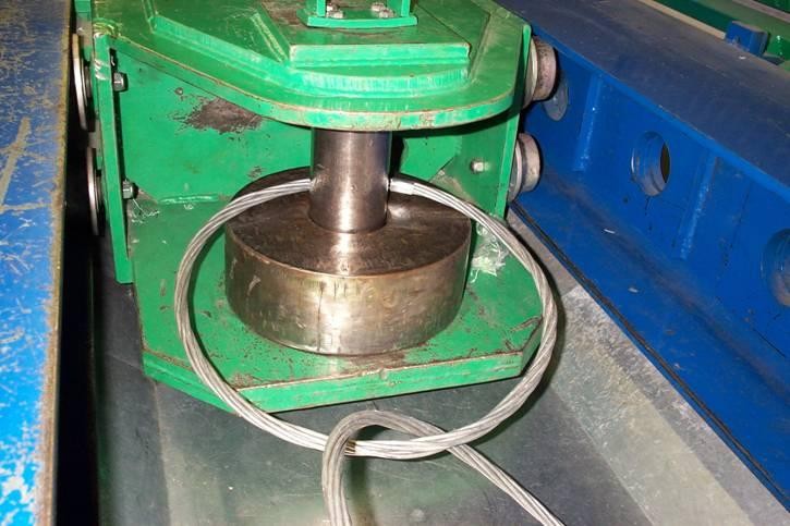
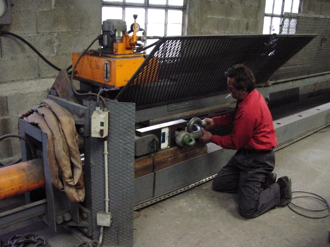
Live Impact Tests
The following tests demonstrate the mesh behaviour under dynamic impact loading — filmed during certified testing conducted in Europe. The controlled deformation and energy absorption visible in these tests are the physical basis for the ≥5,000 kJ performance rating.
European Laboratory Certification
The performance data cited in this article is drawn from independent European laboratory testing — not manufacturer claims. The following documentation covers three levels of verification: component testing, comparative net analysis, and full tensile certification.
| Net Type | Ring Ø | Wire Ø | Resistance (T) | Zinc (g/m²) |
|---|---|---|---|---|
| ASM 420×18×4 | 420 mm | 4 mm | 50 T | 220 |
| ASM 350×12×4 | 350 mm | 4 mm | 22 T | 220 |
| ASM 350×9×3 | 350 mm | 3 mm | 16 T | 220 |
The key figure from direct certification: a single ring of 420mm diameter fails at 45 tonnes — equivalent to 441 kN. This is the measured rupture load on calibrated laboratory equipment, not a calculated estimate. The CITEM comparative table shows that new nets with 220 g/m² zinc protection achieve resistance values of 16–50 tonnes depending on configuration — all well above any UAV threat class impact load.
Comparison: Chainmail vs Conventional Mesh
To understand why conventional industrial mesh is not an appropriate substitute, consider the key performance differences:
Certification and Validation
The performance data cited in this article is not theoretical — it is drawn from certified testing and registered intellectual property. The mesh has been validated through the following:
The mesh technology has an established track record in demanding civil engineering applications — rockfall protection in mountain regions, port barrier systems, river bank reinforcement, and oil and gas infrastructure protection. These are environments with real dynamic loading conditions, real UV and corrosion exposure, and real consequences if the mesh fails.
Gulf Climate Considerations
The UAE and Gulf region present specific environmental challenges for any metallic mesh system deployed on outdoor infrastructure. Surface temperatures on uninsulated steel can exceed 80°C in summer months. Salt-laden air in coastal locations like Fujairah or Ras Al Khaimah accelerates corrosion. UV radiation degrades polymer-based coatings.
The chainmail mesh addresses these conditions in two ways. First, the hot-dip galvanised zinc coating provides ISO 12944-grade corrosion protection — the same standard applied to the structural framework of the system. Second, the all-steel construction contains no polymer components that degrade under UV exposure. The 50-year service life certification is based on real environmental exposure, not idealised laboratory conditions.
In practice, the mesh requires minimal maintenance. Periodic visual inspection — which can be performed without entering the protected zone — is sufficient to confirm integrity. Individual ring sections can be replaced locally if damage occurs, without removing the structural framework or interrupting tank operations.
How the Mesh Integrates with the Structural System
The chainmail mesh is not simply draped over the structural framework — it is engineered into the load path of the system. The outer mesh layer attaches to the ring beams at defined connection points, with sufficient slack to allow controlled deformation under impact without transferring excessive loads to the ring beams or columns.
The double-layer mesh option — available in MEDIUM and HEAVY protection levels — provides a second mesh layer offset inward from the outer layer. If the outer layer is deformed by an impact, the inner layer provides a secondary barrier. The gap between layers also contributes to energy dissipation through controlled deformation sequence.
The mesh-to-framework connection details are specified in the detailed engineering package for each project. Connection hardware is stainless steel or hot-dip galvanised to match the mesh corrosion protection class.
Summary for engineering review: The chainmail mesh used in this system has certified tensile strength of 415 kN/m, single ring failure load exceeding 100 kN, and dynamic impact absorption capacity of ≥5,000 kJ — representing a safety margin of approximately 400× against a Threat Class B impact and 55× against Threat Class C. Service life is 50 years with hot-dip galvanised zinc corrosion protection. Performance is supported by European laboratory testing, three registered patents, and GOST R conformity certification.